



NEWS&EVENTS
As the core equipment for copper ion extraction and separation in hydrometallurgy, the copper extraction tank is designed around the requirements of mixing, separation, flow control, and corrosion resistance. A typical component is as follows:
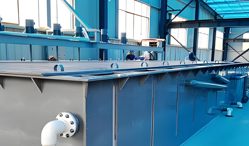
Mixing chamber
The mixing chamber is the initial functional area of the extraction tank. Through mechanical stirring (such as paddle or spiral stirrers) or pulse jetting, the copper solution to be extracted (aqueous phase) and the extractant (organic phase) are brought into full contact. During mixing, copper ions transfer from the aqueous phase to the organic phase, completing mass transfer. The mixing chamber is typically equipped with a feed inlet and overflow baffles to ensure that the material enters in the correct proportion and to prevent short-circuiting. The mixing time is generally controlled at 5-10 minutes to ensure extraction efficiency.
Clarification chamber
The mixed emulsion enters the clarification chamber, where it separates into layers under gravity. The denser aqueous phase (containing residual impurities) settles to the bottom, while the less dense organic phase (enriched with copper ions) floats to the top. The clarification chamber may be equipped with baffles, sedimentation tanks, or filters to further reduce eddies, promote impurity settling, and improve separation purity. Some designs shorten clarification time and reduce dispersion thickness by optimizing the clarification chamber path or adding agitators.
Interstage
Interstage inlets connect adjacent extraction stages and are divided into organic phase interstage inlets and aqueous phase interstage inlets. Their varying elevations utilize gravity to drive liquid flow, ensuring that the mixture passes through each extraction tank sequentially along the designed path, achieving multi-stage countercurrent extraction and improving copper recovery rates (up to 99% or more).
Tank and Material
The tank body must be resistant to corrosion from acidic solutions. Common materials for copper extraction tanks include stainless steel (such as 316L), polypropylene (PP), polyvinylidene fluoride (PVDF), or Hastelloy.